


rate of the link while others are based on absolute values. For scalable
timing parameters based on the TMDS clock rate (Transition Minimized
Differential Signaling Clock Rate), the time period of the clock is denoted
as 'TMDS character time', or, 'Transition Minimized Differential Signaling
Character Rate', or Tcharacter. One tenth of the character time is called
the bit time, or Tbit. The bit time is also referred to as one Unit
Interval in the jitter and eye diagram specifications.
Schematic diagrams contained in this chapter are for illustration only and
do not represent the only feasible implementation.
Transition Minimized Differential Signaling Overview (TMDS Overview)
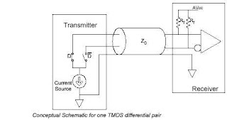
The conceptual schematic of one TMDS (Transition Minimized Differential
Signaling) differential pair is shown in 'Conceptual Schematic for one TMDS
(Transition Minimized Differential Signaling) differential pair' Figure.
(See attached file: Conceptual schematic for one TMDS differential
pair.jpg) TMDS technology (transition minimized differential signaling
technology) uses current drive to develop the low voltage differential
signal at the Sink side of the DC-coupled transmission line. The link
reference voltage AVcc sets the high voltage level of the differential
signal, while the low voltage level is determined by the current source of
the HDMI Source and the termination resistance at the Sink. The termination
resistance (RT) and the characteristic impedance of the cable (Z0) must be
matched.
A single-ended differential signal, representing either the positive or
negative terminal of a differential pair, is illustrated in 'Single-ended
differential signal' Figure. (See attached file: Single-ended differential
signal.jpg) The nominal high-level voltage of the signal is AVcc and the
nominal low-level voltage of the signal is (AVcc - Vswing). Since the swing
is differential on the pair, the net signal on the pair has a swing twice
that of the single-ended signal, or 2 Vswing. The differential signal, as
shown in 'Differential signal' Figure, (See attached file: Differential
signal.jpg) swings between positive Vswing and negative Vswing.
The signal test points for a TMDS link (Transition Minimized Differential
Signaling Link) are shown in 'TMDS Link Test Points' Figure. (See attached
file: TMDS Link Test Points.jpg) TP1 is used for testing of HDMI Sources
and Transmitter components. TP2 is used for testing of HDMI Sinks and
Receiver components. TP1 and TP2 together are also used for testing of
cables.

No comments:
Post a Comment